News:

Welcome to the Tormek Community. If you previously registered for the discussion board but had not made any posts, your membership may have been purged. Secure your membership in this community by joining in the conversations.

www.tormek.com

Main Menu
Menu

Show posts

This section allows you to view all posts made by this member. Note that you can only see posts made in areas you currently have access to.

Show posts Menu

Messages - smurfs

#1
Quote from: tgbto on April 10, 2022, 05:36:40 PM
Still, I am not sure why one would prefer taking three measurements (both measurements shown here plus the one at sharpening time) compared to only one from USB to top of wheel...

tgbto, the measurements described are performed just once and the constants are stored as configuration settings in the calculators that require them.

Quote from: Ken S on April 10, 2022, 10:14:20 PM
I do not understand "notoriously difficult to measure, even for the most skilled".

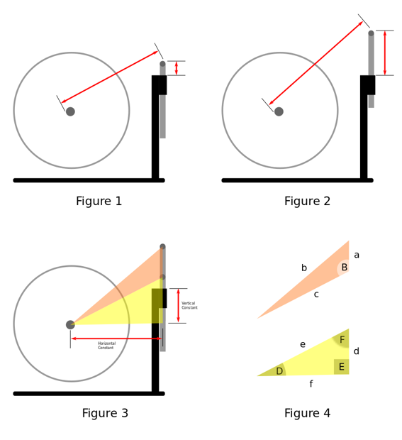
Ken, with respect you misread my first sentence "The horizontal and vertical constants used by various calculators to determine the support bar height from a given origin, such as the machine cover or support bar sleeve, are notoriously difficult to measure physically, even for the most skilled."

Andrew
#2
The horizontal and vertical constants used by various calculators to determine the support bar height from a given origin, such as the machine cover or support bar sleeve, are notoriously difficult to measure physically, even for the most skilled. Additionally, if steps are not first taken to ensure the support bar legs are perpendicular to the horizontal running through the wheel axle center prior to measurement, the degree of inaccuracy in calculated bar height will increase the further the support bar is raised from the initial point of measurement.

To overcome these issues I have derived a new method of computing the constants mathematically which is quick and easy and requires no particular skill. As a bonus the math/s used also implicitly caters for any variance from perpendicular of the support bar and mounting at any height, which is particularly useful in home-made bar mountings made from off the shelf components not precision engineered, such as those used in slow-speed honing setups.

The method is machine agnostic and can be applied to any support bar mounting position. It simply requires measurement of the distance between the support bar and wheel axle, and the support bar and sleeve face/mounting/cover, at two different heights. Obviously the accuracy of the constant results will depend on the accuracy of these two sets of measurements, so if necessary check and/or rerun the measurements at different heights should you have any doubts.

The only equipment required are vernier calipers, preferably 300mm.

Here are the steps which would apply to a slow-speed honing setup with both left and right mountings (*):

1. Remove the wheel from the axle.
2. Insert the support bar fully into the mounting sleeve and fasten.
3. Measure and record the outside distance between the axle and support bar (figure 1). Ensure the calipers are parallel to the axle and bar centers.
4. Measure and record the vertical height from the bar top to XB-100 sleeve/housing (figure 1). Ensure the caliper depth gauge is parallel to the threaded bar leg.
5. Raise the support bar by a meaningful distance, say 10 to 15cm, and fasten (figure 2).
6. Repeat steps 3 & 4.

* Actually the procedure is identical for any support bar mounting point. Also note outside measurements are adjusted to center-to-center distances prior to constant calculation.


As depicted in figure 3 the two sets of measurements form a triangle, shown in orange, the sides of which are the distances between the centers of the wheel axle and support bar inserted, the wheel axle and support bar extended, and the difference in support bar heights. The yellow triangle contains the horizontal and vertical constants which historically have been derived through physical measurement.

The math/s is relatively straightforward and is described below for those interested.

For those that glaze over at the thought I have put together a simple DEMO spreadsheet to compute the constants in the above example which you can [download here]. First update the diameter of your slow speed grinder wheel axle, enter your recorded distances and the constants will be displayed. All that remains is to transfer the values to the software that requires it. By the way the spreadsheet as currently designed applies equally to the Tormek vertical mounting and only requires slight modifying for the FVB and horizontal mountings (@jvh, could a utility to determine all constants be included within TormekCalc?).

Now to the math/s.

Using the known three sides of the orange bar-axle triangle (figure 4) we determine angle B, which incidentally is the bit that handles any variability in perpendicular; if the bar leans slightly toward the machine the computed angle is more acute, and if it leans away is more obtuse. This is important as it impacts directly on the constant lengths which are ultimately derived from it.


Next we determine angles D and F in the yellow constants triangle (note that angle E is a right angle and therefore never changes).


We know the length of side e is the same as side c, so the lengths of the two remaining sides from which the vertical and horizontal constant values are derived are computed thus:


and


In this example the vertical constant should be reduced by the height of the previously recorded lower vertical height from the bar top to XB-100 sleeve/housing (step 3 above), plus the support bar diameter. This is because the origin of the height measurement is the face of the XB-100 sleeve/housing, so subtract this distance from the length of side d.

The horizontal constant needs no adjustment so equals the length of side f.

That's it.

If necessary constants may be cross-checked using TormekCalc, viz, for any given bar height you can expect the height of the support bar to bar height origin (sleeve/cover/etc) to correspond to the height of the bar to the wheel surface.

Hopefully this method will put an end to the polarizing discussion around which bar height measurement approach is best as they are now equally valid and accurate  ;)

#3
Knife Sharpening / Re: Stands
April 04, 2022, 12:50:42 AM
Quote from: Sir Amwell on March 31, 2022, 12:46:18 AM
As a slight diversion. However you decide to proceed with your stands a word of caution. Your stands must be perpendicular to the surface your grinder is mounted on. If not your constant horizontal measurement will vary as you raise or lower the support bar and whatever software you use to determine angle will be inaccurate. Another way to consider this: using Vadim's set up method for your slow speed grinder relies on that horizontal measurement to be constant at base level ( recommended 125mm I believe). If your stand is not perpendicular then up at the support bar level it will be out of alignment. Taking an accurate horizontal measurement is EXTREMELY difficult at the top end. The problem being is that even following Vadim's set up procedure with his stands ( which are truly square) fixing them to a work surface throws out the square by tightening the fixings. 300mm above this causes problems. Ie 0.5 mm discrepancy at base level is exaggerated 300mm above that. If anyone knows how to overcome this it would be truly helpful for everyone who has problems with set up for this system of burr removal. Sadly Vadim is no longer here to guide us through this.

The inaccuracy in perpendicular alignment can be overcome mathematically using an alternative approach to computing the support bar height from a given height origin, for example machine cover, sleeve face, etc., by replacing the step that relies on the constant vertical and horizontal dimensions. Note the bar to wheel height calculation remains unchanged.

The method I have come up with is machine agnostic and can be applied to any mounting point configuration. It was developed to solve two problems, namely:

1. To overcome the perpendicular alignment problem you have described, and;
2. To determine/define the minimum and maximum support bar physical operating height constraints in each mounting position.

The second point is business logic specific and ensures the calculated support bar height result (bar to wheel, and/or bar to some other height origin) is constrained to the bar range of operation for a particular mounting point. This is implemented in a database backed Android app I developed for my business.

The method is reliant on the scalene triangle formed between the wheel axle, the support bar fully inserted, and the support bar fully extended, for each combination of mounting and support bar. I haven't got around to documenting the math so I'll simply describe how the measurements are recorded for the Tormek vertical mounting point. Suffice to say the approach to measuring is the same for horizontal and FVB mountings.

With the wheel removed, insert the support bar fully in the sleeve. Measure the center-to-center distance between the wheel axle and support bar horizontal, then the support bar center to machine cover. This is the first set of measurements. Now extend the bar fully. It doesn't matter how high you set the bar so long as it can be safety used at this height. Now repeat the measurements with the bar in this position. It is important that the same height origin is used for both sets of measurements, in this example the machine cover (incidentally the axle to bar measurements are also used in bar-to-wheel constraint calculations too).

As you will see the measurements form a triangle of three known sides from which all unknowns can be determined, viz axle center to bar center at highest point, axle center to bar center at lowest point, bar center at highest point to bar center at lowest point (length of vertical side is the delta of both measurements).

One important property of this triangle is the largest angle formed between the axle center, bar center (low) and bar center (high) is fixed. In other words once it is determined it remains constant no matter the calculated height of the bar. So the bar could be 5 degrees off vertical and it won't affect either the bar height to origin nor blade projection measurements at any height. This neatly addresses the problem of point 1 above.

This has turned into a bit of a long winded explanation so I'll stop rambling now. To those interested in the math I will endeavour to write up steps and formulae in the next month or so.

As for the Android app I had no intention of releasing it as I didn't want to cannibalize Wootz's app income stream given others were commercializing his research and efforts without recompense. Obviously things have changed with his passing so I will revisit this decision and possibly release it gratis via the app store in the near future.
#4
Quote from: Hannsi1957 on July 18, 2020, 02:33:18 PM
In principle it does not matter which medium you use because the results are not comparable.It depends on several factors that have too many sources of error to compare better values. On my youtube channel I have made an example video. With the same knife you can compare values from 50 to 120 bess. This device is great but only to test yourself. Comparing with others is very inaccurate.
So it dont matter witch medium u use. Use it 4 urselve.

Hello Hanns,

It hadn't occurred to me that speed of the sharpness test could affect the BESS reading so I found your video demo interesting too.

However variations in the tension of the test media in the holder could also contribute to wide ranging results you observed. To rule this out you ought to ensure the media tension is the same in each test. SharpCo, another forum member, demonstrates in this video how to do this.

I'd be interested to see you rerun these tests again to compare the scores you get.

Regards, Andrew

#5
Wootz at Knife Grinders uses this approach in volume sharpening documented here, so yes it works but you will have to devise a jig system.

Edit: fixed hyperlink
#6
Tormek T-1 and T-2 / Re: Tormek online T2 class
June 25, 2020, 07:36:43 PM
Ken, I have Wootz's book and have read it several times so appreciate the problem of wire edges and low quality knives... I just overlooked the issue in my initial excited assessment of the T2.

I've managed to get a copy of the T2 manual and lo and behold on page 6 it states...

QuoteThe burr can sometimes (depending on the quality of the steel) bend to one side and then the other, therefore it is sometimes better to hone alternately between the sides. If the burr is not honed away, the knife can feel dull, even though it is "freshly sharpened".

So, in short, my idea to offer a T2 budget service for low quality knives will not fly as the problem of the malleable burr remains. That said I am glad I explored the idea. I will continue to follow Wootz's protocols using paper wheels and will look for efficiencies elsewhere.
#7
Tormek T-1 and T-2 / Re: Tormek online T2 class
June 25, 2020, 09:40:41 AM
I've parked the idea of getting a T2 for the moment based purely on the cost. The T2 plus coarse diamond wheel leaves little change from EUR1000 which makes it approximately twice the cost of a T4 / T8 with no accessories. At that price I think I'd be more inclined to get an additional 2xT8's simply to reduce the inconvenience/time taken to change wheels when sharpening!

BeSharp that's interesting and something I'm willing to give a try. Can you expand on the progression of paper wheel grits you use? Thanks
#8
Tormek T-1 and T-2 / Re: Tormek online T2 class
June 21, 2020, 08:16:43 PM
Thank you for doing this exercise Ken.

The 210 BESS result falls just outside the "Very sharp" BESS classification which I'd imagine is sharper than what it was when new. To my mind this is a very good result and is more than adequate for the budget sharpening service I outlined.

I need to do a little more research but think it is highly likely I'll be getting a T2 to cater for the budget conscious.

Thanks again, Andrew
#9
Tormek T-1 and T-2 / Re: Tormek online T2 class
June 19, 2020, 08:51:01 AM
Many thanks Ken.

Interestingly I had a similar thought regarding the steak knives when they discussed them in the video.

I look forward to your test results as I think we may be in for a surprise i.e. BESS 100-200
#10
Tormek T-1 and T-2 / Re: Tormek online T2 class
June 18, 2020, 10:32:09 PM
I enjoyed the T2 class too and can see why the quick and simple sharpening process would immediately appeal to professional chefs interested in the DIY sharpening option.

It did occur to me when watching the video that the T2 may also be useful to professional sharpeners like myself, especially when sharpening low quality knives for customers who would be happy/willing to accept a good working edge e.g. BESS 250 to 400, at a much reduced price point, simply based on the quicker sharpening process. The market I think may benefit from a budget sharpening service are home chefs, who in my neck of the woods at least don't appear to own too many quality knives as I discovered while keeping busy during the lockdown :)

So the question I would like to pose to those who own a T2 and BESS tester is "what is the lowest BESS score achievable with the T2?". Anyone out there have the answer?

Cheers, Andrew
#11
Hi Ernst

I suspect it is just cosmetic due to poor assembly which is unacceptable given the cost of the item.

When I received my Catra Hobby the clear perspex parts containing the V notches were covered in excess glue and even had the assemblers glue fingerprint marks in places. Worse still was the laser beam was not correctly aligned and straddled the 1 degree mark. I sent it back immediately for a replacement which was only marginally better - the laser alignment was still an issue but not as bad.

I strongly recommend you send it back if you are not happy with it. Perhaps even ask for a refund and look at other options, which in hindsight is something I should have done.

Andrew
#12
Knife Sharpening / Re: Goniometer - MASTER
March 25, 2020, 07:32:03 PM
Quote from: van on March 25, 2020, 01:17:34 AM
Thanks JVH,
excellent explanation, if you or someone else has other insights to be able to divulge mer better understand the reading on laser protractors, I invite him to publish his knowledge on the matter.
Thank you all.

Hi van

I've scanned and attached the Catra laser protractor user instruction leaflet.

The Vertako and Catra protractors have a similar operation so you may find some of the info of use.

Andrew
#13
Just giving the heads-up to those in Europe that Wolfknives Feines Werkzeug & Handwerk, based in Germany, are now manufacturing and selling their own FVB for €79 - see product description here (in German).

It probably won't be compatible with the Knife Grinders software but will be easier enough to configure with TormekCalc developed by jvh
#14
Quote from: RickKrung on March 04, 2020, 02:52:56 PM
<snip>
Using the off-the-shelf M12 coupler has great possibilities, as you have shown. How does it track in perpendicular rotation (wobble)?     

Rick, if only I had your skills I would have made my own too!
There is not much wobble to speak of. This is my first foray into youtube posting so here is a short clip to demonstrate it in action.

Quote from: cbwx34 on March 04, 2020, 03:11:00 PM
Can you get a longer 'coupling nut' for more clearance?

Curtis (cbwx34), I bought the coupler from Amazon. I see there is a 50mm option available but I'm not sure if they come any longer than that.


P.S. SHARPCO, apologies for unintentionally hijacking this thread. Ken, perhaps this content should be moved to its own?
#15
Quote from: RickKrung on March 03, 2020, 03:25:00 PM

I will be very interested to hear what you find and think.  I am now using the SJ stone as the first step in honing and 1 micron diamond paste on a rock hard felt wheel as the final stage.  Both of these depend very heavily on precise angle control and different final angles for different steels, all based on Knife Grinders' work.

It would be very handy to have the 1 micron on the leather wheel side rather than having another wheel change on the stone side.  I wonder if the leather wheel will be hard enough to function well with the 1 micron media. 

I have visions of adapting the 10" felt wheel to go on the leather wheel side, but it would have to be off when grinding, which I don't always have to do with the leather wheel.  But, since I'm not using the leather wheel in the above process, it doesn't need to be there. 

Rick,

I bought off the shelf items to attach a split-lap felt wheel on the leather wheel side of the Tormek to sharpen serrations (as per Wootz' video). It takes minimal time to switch out the leather wheel and could work for you too.

All that's needed is a M12 bolt (length determined by felt wheel thickness), 2x M12 flat washers and a M12 40mm coupling nut. Here are a couple of pics.

Incidentally the only drawback I have encountered in my set up, which is due to small diameter of the felt wheel, is the grinding wheel gets in the way when tackling serrations on the left hand side of the blade. In these cases I have to remove the grinding wheel. It is not such an issue when the serrations are on the opposite side of course.

Andrew