The horizontal and vertical constants used by various calculators to determine the support bar height from a given origin, such as the machine cover or support bar sleeve, are notoriously difficult to measure physically, even for the most skilled. Additionally, if steps are not first taken to ensure the support bar legs are perpendicular to the horizontal running through the wheel axle center prior to measurement, the degree of inaccuracy in calculated bar height will increase the further the support bar is raised from the initial point of measurement.
To overcome these issues I have derived a new method of computing the constants mathematically which is quick and easy and requires no particular skill. As a bonus the math/s used also implicitly caters for any variance from perpendicular of the support bar and mounting at any height, which is particularly useful in home-made bar mountings made from off the shelf components not precision engineered, such as those used in slow-speed honing setups.
The method is machine agnostic and can be applied to any support bar mounting position. It simply requires measurement of the distance between the support bar and wheel axle, and the support bar and sleeve face/mounting/cover, at two different heights. Obviously the accuracy of the constant results will depend on the accuracy of these two sets of measurements, so if necessary check and/or rerun the measurements at different heights should you have any doubts.
The only equipment required are vernier calipers, preferably 300mm.
Here are the steps which would apply to a slow-speed honing setup with both left and right mountings (*):
1. Remove the wheel from the axle.
2. Insert the support bar fully into the mounting sleeve and fasten.
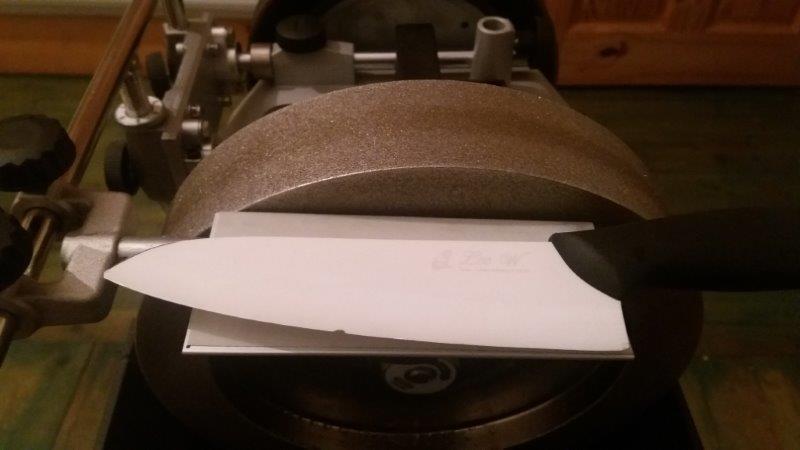
3. Measure and record the outside distance between the axle and support bar (figure 1). Ensure the calipers are parallel to the axle and bar centers.
4. Measure and record the vertical height from the bar top to XB-100 sleeve/housing (figure 1). Ensure the caliper depth gauge is parallel to the threaded bar leg.
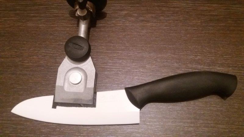
5. Raise the support bar by a meaningful distance, say 10 to 15cm, and fasten (figure 2).
6. Repeat steps 3 & 4.
* Actually the procedure is identical for any support bar mounting point. Also note outside measurements are adjusted to center-to-center distances prior to constant calculation.
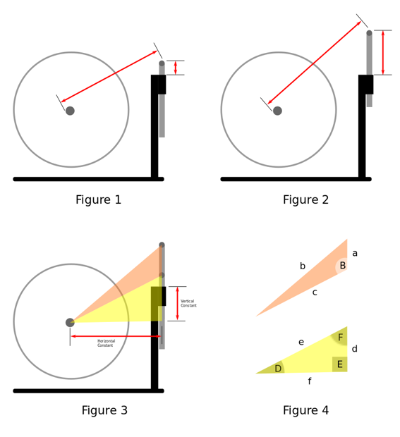
As depicted in figure 3 the two sets of measurements form a triangle, shown in orange, the sides of which are the distances between the centers of the wheel axle and support bar inserted, the wheel axle and support bar extended, and the difference in support bar heights. The yellow triangle contains the horizontal and vertical constants which historically have been derived through physical measurement.
The math/s is relatively straightforward and is described below for those interested.
For those that glaze over at the thought I have put together a simple DEMO spreadsheet to compute the constants in the above example which you can [download here]. First update the diameter of your slow speed grinder wheel axle, enter your recorded distances and the constants will be displayed. All that remains is to transfer the values to the software that requires it. By the way the spreadsheet as currently designed applies equally to the Tormek vertical mounting and only requires slight modifying for the FVB and horizontal mountings (@jvh, could a utility to determine all constants be included within TormekCalc?).
Now to the math/s.
Using the known three sides of the orange bar-axle triangle (figure 4) we determine angle B, which incidentally is the bit that handles any variability in perpendicular; if the bar leans slightly toward the machine the computed angle is more acute, and if it leans away is more obtuse. This is important as it impacts directly on the constant lengths which are ultimately derived from it.
)
Next we determine angles D and F in the yellow constants triangle (note that angle E is a right angle and therefore never changes).


We know the length of side e is the same as side c, so the lengths of the two remaining sides from which the vertical and horizontal constant values are derived are computed thus:
%7D%20%7Bsin(E)%7D)
and
%7D%20%7Bsin(E)%7D)
In this example the vertical constant should be reduced by the height of the previously recorded lower vertical height from the bar top to XB-100 sleeve/housing (step 3 above), plus the support bar diameter. This is because the origin of the height measurement is the face of the XB-100 sleeve/housing, so subtract this distance from the length of side d.
The horizontal constant needs no adjustment so equals the length of side f.
That's it.
If necessary constants may be cross-checked using TormekCalc, viz, for any given bar height you can expect the height of the support bar to bar height origin (sleeve/cover/etc) to correspond to the height of the bar to the wheel surface.
Hopefully this method will put an end to the polarizing discussion around which bar height measurement approach is best as they are now equally valid and accurate
To overcome these issues I have derived a new method of computing the constants mathematically which is quick and easy and requires no particular skill. As a bonus the math/s used also implicitly caters for any variance from perpendicular of the support bar and mounting at any height, which is particularly useful in home-made bar mountings made from off the shelf components not precision engineered, such as those used in slow-speed honing setups.
The method is machine agnostic and can be applied to any support bar mounting position. It simply requires measurement of the distance between the support bar and wheel axle, and the support bar and sleeve face/mounting/cover, at two different heights. Obviously the accuracy of the constant results will depend on the accuracy of these two sets of measurements, so if necessary check and/or rerun the measurements at different heights should you have any doubts.
The only equipment required are vernier calipers, preferably 300mm.
Here are the steps which would apply to a slow-speed honing setup with both left and right mountings (*):
1. Remove the wheel from the axle.
2. Insert the support bar fully into the mounting sleeve and fasten.
3. Measure and record the outside distance between the axle and support bar (figure 1). Ensure the calipers are parallel to the axle and bar centers.
4. Measure and record the vertical height from the bar top to XB-100 sleeve/housing (figure 1). Ensure the caliper depth gauge is parallel to the threaded bar leg.
5. Raise the support bar by a meaningful distance, say 10 to 15cm, and fasten (figure 2).
6. Repeat steps 3 & 4.
* Actually the procedure is identical for any support bar mounting point. Also note outside measurements are adjusted to center-to-center distances prior to constant calculation.
As depicted in figure 3 the two sets of measurements form a triangle, shown in orange, the sides of which are the distances between the centers of the wheel axle and support bar inserted, the wheel axle and support bar extended, and the difference in support bar heights. The yellow triangle contains the horizontal and vertical constants which historically have been derived through physical measurement.
The math/s is relatively straightforward and is described below for those interested.
For those that glaze over at the thought I have put together a simple DEMO spreadsheet to compute the constants in the above example which you can [download here]. First update the diameter of your slow speed grinder wheel axle, enter your recorded distances and the constants will be displayed. All that remains is to transfer the values to the software that requires it. By the way the spreadsheet as currently designed applies equally to the Tormek vertical mounting and only requires slight modifying for the FVB and horizontal mountings (@jvh, could a utility to determine all constants be included within TormekCalc?).
Now to the math/s.
Using the known three sides of the orange bar-axle triangle (figure 4) we determine angle B, which incidentally is the bit that handles any variability in perpendicular; if the bar leans slightly toward the machine the computed angle is more acute, and if it leans away is more obtuse. This is important as it impacts directly on the constant lengths which are ultimately derived from it.
Next we determine angles D and F in the yellow constants triangle (note that angle E is a right angle and therefore never changes).
We know the length of side e is the same as side c, so the lengths of the two remaining sides from which the vertical and horizontal constant values are derived are computed thus:
and
In this example the vertical constant should be reduced by the height of the previously recorded lower vertical height from the bar top to XB-100 sleeve/housing (step 3 above), plus the support bar diameter. This is because the origin of the height measurement is the face of the XB-100 sleeve/housing, so subtract this distance from the length of side d.
The horizontal constant needs no adjustment so equals the length of side f.
That's it.
If necessary constants may be cross-checked using TormekCalc, viz, for any given bar height you can expect the height of the support bar to bar height origin (sleeve/cover/etc) to correspond to the height of the bar to the wheel surface.
Hopefully this method will put an end to the polarizing discussion around which bar height measurement approach is best as they are now equally valid and accurate