I thought I would post an update.
My goal was to make a metal lathe tool grinding jig that was adjustable for angles in all three axis.
As you have seen in this thread metal lathe tools have been ground successfully on high speed grinders for generations with no problem.
I just wanted a bit more accuracy and buying a low speed grinder is a perfect excuse for making this jig.
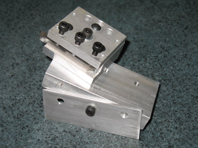
Here is an overview.
This is a working "proof of concept" prototype. I still need to clean off all the layout dye, chamfer edges, install the adjustable angle indicators and paint.
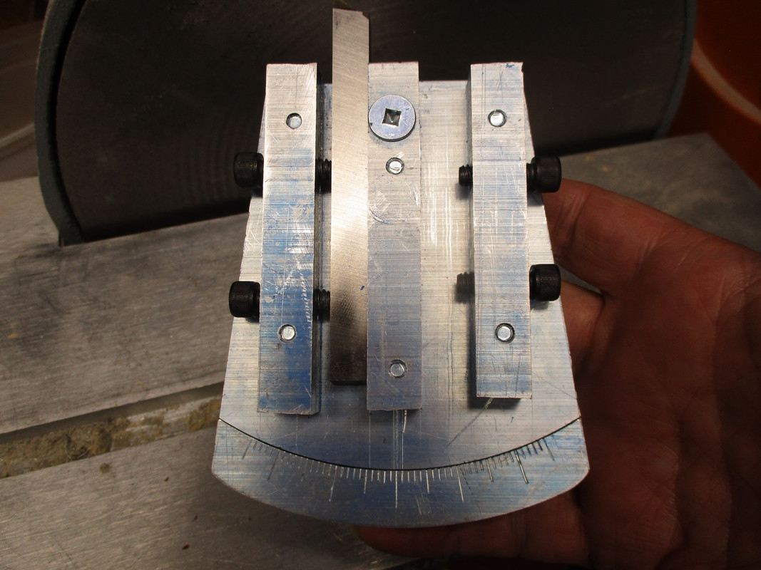
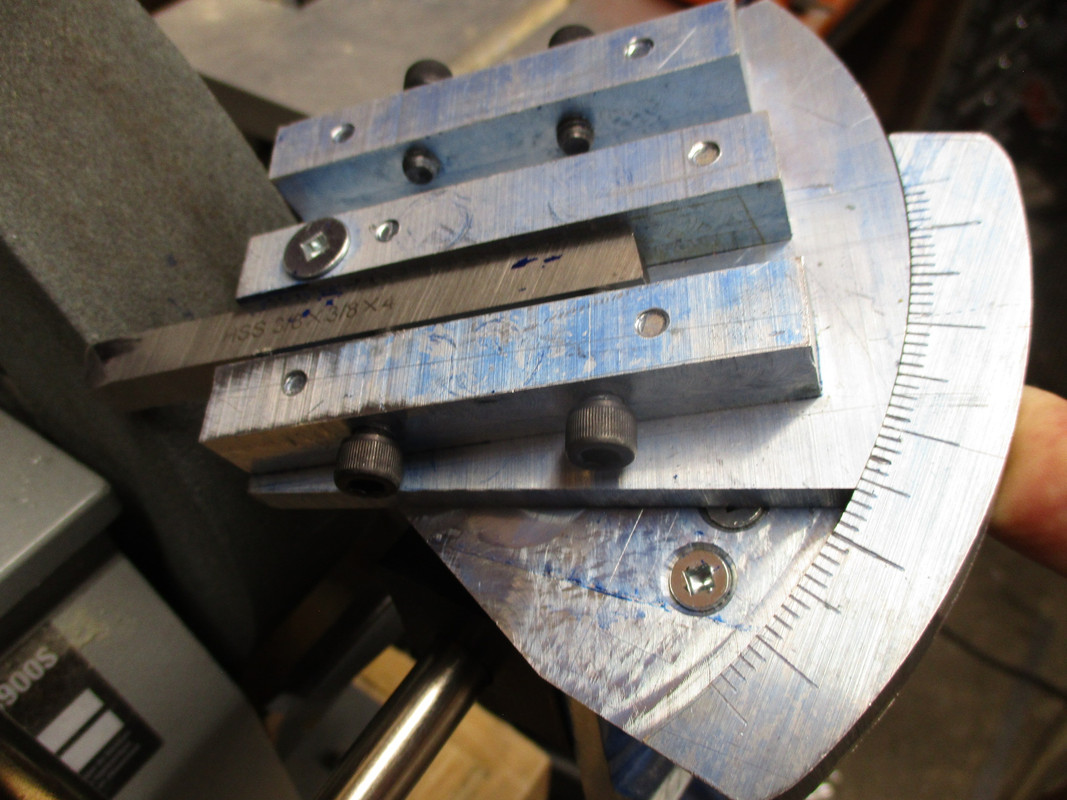
This is from above. You can see the left and right tool clamps and the horizontal angle scale.
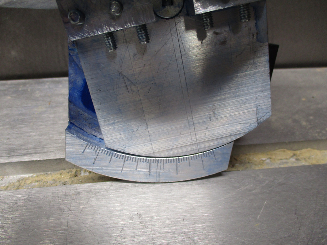
Looking from the front you can see the vertical angle scale.
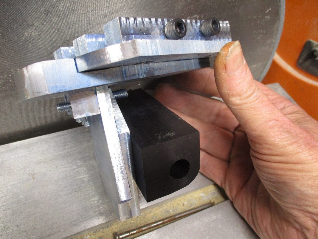
To fit over the rest rod I drilled a hole in some scrap Delron.
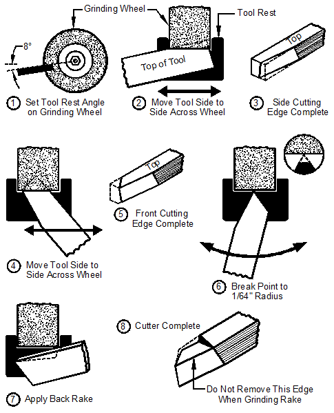
The first step in grinding a metal lathe tool is to create the "Side Cut Angle" The angle for the Side Cut Angle is comprised of two axis. It is ground on the right side of the grinding wheel.
The horizontal scale is set to 10¯ deg°and the vertical is set to 10°.
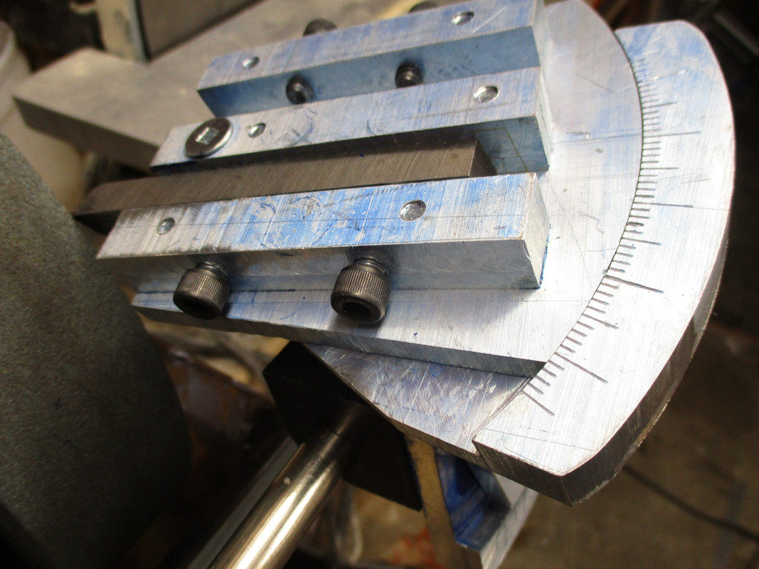
Second, you grind the "End Cut Angle" This is also two axis with the approach to the face of the wheel being one angle of 12° and the horizontal scale set to 20°. The vertical scale is set to 0°.
This setting gives a 110° single point relief.
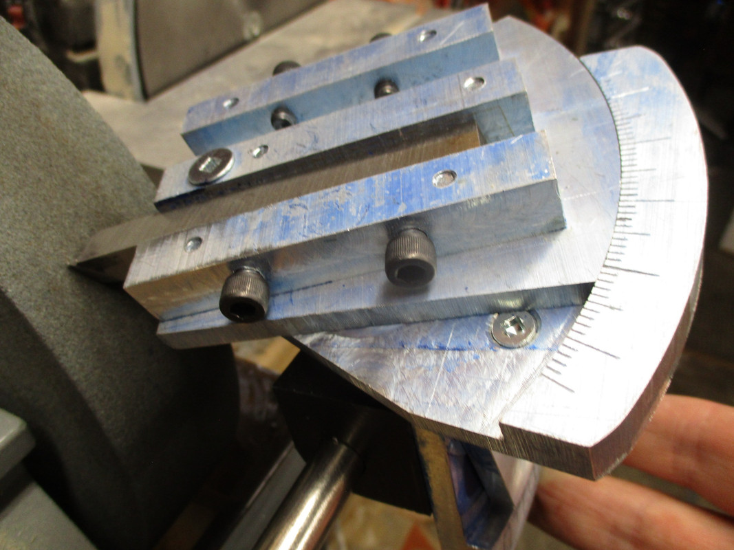
Finally the Back and Side Rake Angles are ground. This is done on the left side of the wheel.
This lathe tool is specifically for use on Delron so the Back Rake Angle is set on the Horizontal scale at 26°. The vertical scale is set to 10°.
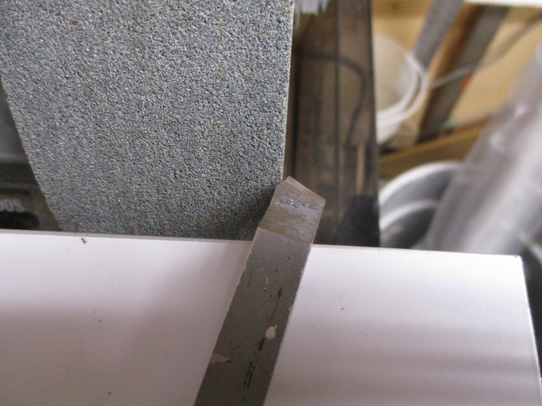
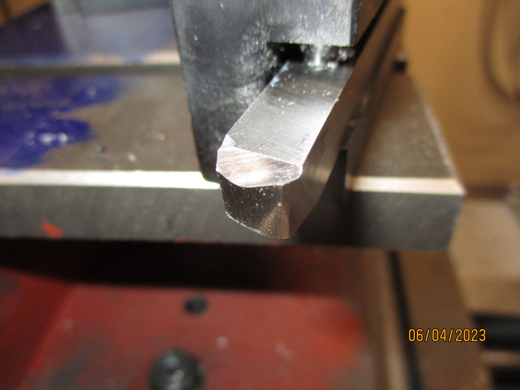
Here is a close up of the finished lathe tool.
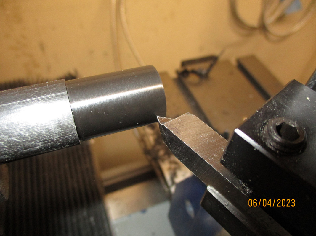
Not too bad a cut.
The reason I chose to grind this particular tool first is that my next project has parts made from Delron. Delron requires very sharp edges and larger Back Rake Angles than tools used to cut steel. I thought a Delron cutting tool would be a good first attempt.
I have CBN wheels inbound from Australia and that should be just a bit better than always facing the right and left sides of the standard grinding wheel.
My goal was to make a metal lathe tool grinding jig that was adjustable for angles in all three axis.
As you have seen in this thread metal lathe tools have been ground successfully on high speed grinders for generations with no problem.
I just wanted a bit more accuracy and buying a low speed grinder is a perfect excuse for making this jig.
Here is an overview.
This is a working "proof of concept" prototype. I still need to clean off all the layout dye, chamfer edges, install the adjustable angle indicators and paint.
This is from above. You can see the left and right tool clamps and the horizontal angle scale.

Looking from the front you can see the vertical angle scale.

To fit over the rest rod I drilled a hole in some scrap Delron.

The first step in grinding a metal lathe tool is to create the "Side Cut Angle" The angle for the Side Cut Angle is comprised of two axis. It is ground on the right side of the grinding wheel.
The horizontal scale is set to 10¯ deg°and the vertical is set to 10°.

Second, you grind the "End Cut Angle" This is also two axis with the approach to the face of the wheel being one angle of 12° and the horizontal scale set to 20°. The vertical scale is set to 0°.
This setting gives a 110° single point relief.

Finally the Back and Side Rake Angles are ground. This is done on the left side of the wheel.
This lathe tool is specifically for use on Delron so the Back Rake Angle is set on the Horizontal scale at 26°. The vertical scale is set to 10°.

Here is a close up of the finished lathe tool.

Not too bad a cut.

The reason I chose to grind this particular tool first is that my next project has parts made from Delron. Delron requires very sharp edges and larger Back Rake Angles than tools used to cut steel. I thought a Delron cutting tool would be a good first attempt.
I have CBN wheels inbound from Australia and that should be just a bit better than always facing the right and left sides of the standard grinding wheel.

